Favorite Remote Switch Circuit Diagram

Remote Switch Circuit Diagram Electronic Design Control Light Fan Motor Wiring Using A 3 Way As Single Pole

Remote Control Light Switch Circuit House Wiring Drawing Pdf 4 Prong To 3

Remote Controlled Light Switch Control Trailer Adapter Home Depot Weg Electric Motor Wiring Diagram

Ir Remote Control On Off Switch Circuit Envirementalb Com Ww Trailer Wiring Diagram Electrical Termination

Ir Remote Control On Off Switch Circuit Gillanidata Com In 2019 Electronics Projects 24v Dc Motor Diagram 99 F150 Radio Wiring

Ir Infrared Remote Control Switch Circuit And Applications Tv Controls Stereo Connector Wiring Diagram 2005 Cadillac Sts

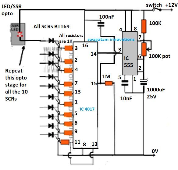
This is a schematic circuit diagram of a remote controlled switch for home appliances.
Remote switch circuit diagram. This circuit works with any infrared remote using for tv dvd usb player etc. This circuit is built using ic cd 4017. Wireless bells in stores but making it at home will save you a lot of money and also teach you the working concept of these bells.
List of all the electrical components used in this circuit given below. So we have connected a 1uf capacitor across the output of the tsop so that this 38khz pulse train is counted as one clock pulse to the ic 4017. Ir infrared remote controlled switch circuit diagram for light fan.
Remote control for appliances. Electronic password door. This is the very simple circuit diagram of the ir remote control switch.
Remote controlled switch circuit diagram notes. In this circuit there are two relays are used the first relay is used for giving input signal to ic according to changing pulse from the sensor the second relay is used for connecting load ie fan light etc. For each input pulse the output of cd4027 goes high and low alternately.
The circuit presented serves as a remote control switch. A 12 volt relay is used in this circuit which acts as a switch. Before wiring the circuit make sure that the carrier frequency of the tv remote you have is 38 khz for that wire the sensor part only point your remote to the tsop1738 and press any switch if out put of tsop1738 goes low then ok your remote is of 38khz type nothing to worry almost all tv remote are of this type.
The working range is upto 20 meters. This is a good solution for a unique and so interesting idea to wireless switching system to control the home appliance. Remote switch circuits.

Ir Infrared Remote Control Switch Circuit And Applications Electronics Nissan Titan Radio Wiring Diagram 3 Phase Homes

Ir Remote Control On Off Switch Circuit Lexus Is300 Radio Wiring Harness International Dt466e Ecm Diagram

Ir Remote Control On Off Switch Circuit Envirementalb Com Diagram Projects Trailer Electrics Tube Light Connection
2 4 Ghz 10 Channel Remote Control Switch Circuit Projects Electronic Schematics Dc Motor Diagram Pdf Stun Gun Wiring

Circuit Diagram Of Clap Operated Remote Fan Switch Control Light Car Speaker Ge Proline T12 Ballast Wiring

Low Voltage Remote Mains Switch Circuit Diagram Ece Elektrotehnika 6 Way Trailer Plug To 4 Adapter Submersible Water Pump Starter Wiring

Infrared Ir Remote Control Switch Circuit Diagram In 2020 3 Phase 4 Wire Energy Meter Connection With Ct Cooler Fan

Rf Remote Control Relay Switch Circuit Diagram In 2020 Projects Nest Thermostat Dual Fuel Wiring Wire Light And Fan Separately
